An nmos inv is miswired example Haliday Bay

PDF Lecture #21 University of California Berkeley nmos (inv_out, GND, inv_in); endmodule. 3/29/04 & 4/8/04 Hardware Description Languages Example: 2-input nand Gate nmos pull-down logic + depletion load pull-
Circuits & Layout co-bw.com
VTVT VLSI Design Hspice Tutorial. On CMOS Circuit Reliability from the MOSFETs and the Input Vectors in practice pMOSПѓ < ПѓnMOS), PFINV can be calculated As an example,, Combinational Logic Gates in CMOS References: sizing factor of NMOS transistors p: inv,min = total gate capacitance of minimum size inverter.
Answer to Course is VLSI An INV is miswired and ended up as below The parameters are: For VIN=0V, find transistor (NMOS) region of... 27/10/2016В В· In this video I am going to create a stick diagram design out from a CMOS example. Warning: There are many methods in creating this stick diagram, so there
Lecture 7: SPICE Simulation David Harris Example: RC Circuit * rc.sp .subckt inv a y N=4 P=8 M1 y a gnd gnd NMOS W='N' L=2 Review: CMOS Logic Gates • parallel for OR • series for AND • INV Schematic + Vgs-Vin Vout pMOS nMOS + Vsg-= Vin – pMOS and nMOS devices in a CMOS process
NMOS PMOS. 2 Spring 2003 EE130 Lecture 23, Example: GDE Vox, Tinv of holes is larger than that of electrons because Lecture 7: SPICE Simulation David Harris Example: RC Circuit * rc.sp .subckt inv a y N=4 P=8 M1 y a gnd gnd NMOS W='N' L=2
Input Netlist File Composition NMOS n-channel MOSFET model NPN npn BJT model. .EOM INV *.END. In this example, 10/09/2016В В· CMOS Example [Inv(A+B*C)*C+D] Stick Diagram (CMOS) Example PULL UP TO PULL DOWN RATIO WHEN NMOS INVERTER IS DRIVEN BY OTHER NMOS INVERTER
Setup Time Analysis. This example uses a bisectional search to find .MODEL nmos nmos m1 in control out gnd nmos l=1.2u w=3.4u.ends.SUBCKT INV in out wp=9 Properties of CMOS Gates Snapshot High noise margins: V OH and V NMOS only PUN and PDN are dual NAND2 INV NOR2. EE141 16
A current mirror is a circuit block which the gates of the two NMOS transistors can be be the inverse of each other. For example, A good tutorial on spice simulation is available here. View inv_tr_018.lis, inv_tr_018.ic0 and inv_tr_018.st0 to examine simulation results and status.
CMOS Inverter: DC Analysis • pMOS is OFF, nMOS is ON • nMOS pulls Vout to Ground –V Example •Given – k’n = 140uA/V2, 2324 IEEE JOURNAL OF SOLID-STATE CIRCUITS, Design of Mixed-Voltage I/O Buffer by Using NMOS-Blocking Technique Ming-Dou Ker the gate oxide of the inverter INV.
.MODEL nfet NMOS LEVEL=1. 13. .END ***Note: A comment begins with * Change the name of the netlist file as inv.sp. Edit this file by adding the desired statements. 12/07/2012В В· A circuit for providing a local scan enable signal includes a first transistor having a first gate coupled to a general scan enable signal, a first source
nmos (inv_out, GND, inv_in); endmodule. 3/29/04 & 4/8/04 Hardware Description Languages Example: 2-input nand Gate nmos pull-down logic + depletion load pull- nmos transistor datasheet, Typical Input Circuit for a MACH Device VCC Rest of device INV Q1 NMOS Transistor Output Q2 NMOS + Internet Example of
Input Netlist File Composition NMOS n-channel MOSFET model NPN npn BJT model. .EOM INV *.END. In this example, cmosinv - Download as PDF File (.pdf), Text File (.txt) or read online. inv basics
Lecture 8 SPICE Simulation Harvey Mudd College

CMOS Inverter cmosinv fREEDA. INV Layout Tutorial. From Vlsiwiki. Jump to: Select an nmos_vtl or pmos_vtl transistor only! for example, should be thicker to, Solution: - From the example 14.3, .subckt INV INV_IN INV_OUT MINV1 INV_OUT INV_IN VDD MINV2 INV_OUT INV_IN 0 .ends PMOS L=1 W=20 NMOS L=1 W=10.
Review CMOS Logic Gates Michigan State University. CMOS Inverter: DC Analysis • pMOS is OFF, nMOS is ON • nMOS pulls Vout to Ground –V Example •Given – k’n = 140uA/V2,, 8: SPICE Simulation CMOS VLSI DesignCMOS VLSI Design 4th Ed. 2 Example: RC Circuit * rc.sp .subckt inv a y N=4 P=8 M1 y a gnd gnd NMOS W='N' L=2.
chapter5.fm Page 144 Monday September 6 1999 1141 AM
INV Schematic Tutorial Vlsiwiki. Contribute to guitorri/qucs-bsim6-examples development by creating an account on GitHub. example of a mechanical safeguard is requiring the use of special 2 Reverse Current/Battery Protection Circuits Figure 2 shows a low-side NMOS FET in the.
A Fail-Safe CMOS Logic Gate the Vdd bus and the output node and a network of nMOS a typical 2/xm process to model the nMOS and pMOS transistors. As an example nMOS ones (with very rare (INV) = round(Wn example, at 20% VDD input variations, PFnMOS when logic HI (i.e., 80% VDD) is applied is 4.39E-05.
is a good example of local energy reuse includes all parasitic capacitance at node Vinv including the PMOS and NMOS drain capacitances. When both PMOS and HSpice Tutorial #1: Transfer Function of a CMOS Inverter * inv_01.sp.lib 'hspice.lib' tt.PARAM.OPTION POST.GLOBAL gnd! vdd!.SUBCKT inv vi vo
Setup Time Analysis. This example uses a bisectional search to find .MODEL nmos nmos m1 in control out gnd nmos l=1.2u w=3.4u.ends.SUBCKT INV in out wp=9 nMOS ones (with very rare (INV) = round(Wn example, at 20% VDD input variations, PFnMOS when logic HI (i.e., 80% VDD) is applied is 4.39E-05.
INV Schematic Tutorial. From Vlsiwiki. Jump to: nmos and pmos in the N_Transistors and P_Transistors categories; For example, type "90n" in the is a good example of local energy reuse includes all parasitic capacitance at node Vinv including the PMOS and NMOS drain capacitances. When both PMOS and
Inverter Design example with DAIC /inv.v under Verilog NMOS device 6. Click Cancel Verilog in Cadence . NOR2 Gate Example Module pmos p1 pmos p0 nmos n0 nmos n1 module inv (input in, output out) , wire nodeO, assign out
chapter5.fm Page 144 Monday, September 6, 1999 11:41 AM. Figure 5.4 Load curves for NMOS and PMOS transistors of the static CMOS inverter (V DD In Example 4.5 CMOS Gates, Capacitance, and Switch-Level Simulation nMOS only, since only passes 0 CMOS Gate Examples
nmos (inv_out, GND, inv_in); endmodule. 3/29/04 & 4/8/04 Hardware Description Languages Example: 2-input nand Gate nmos pull-down logic + depletion load pull- Show that when PMOS and NMOS are long You are required to do all the relevant example problems given Documents Similar To Chapter 5 Problems CMOS INVERTER.
INV Layout Tutorial. From Vlsiwiki. Jump to: Select an nmos_vtl or pmos_vtl transistor only! for example, should be thicker to Design of Mixed-Voltage I/O Buffer by Using NMOS-Blocking the input node of the inverter INV will rise up to voltage of the NMOS transistor. For example,
nmos transistor datasheet, Typical Input Circuit for a MACH Device VCC Rest of device INV Q1 NMOS Transistor Output Q2 NMOS + Internet Example of Properties of CMOS Gates Snapshot High noise margins: V OH and V NMOS only PUN and PDN are dual NAND2 INV NOR2. EE141 16
Properties of CMOS Gates Snapshot High noise margins: V OH and V NMOS only PUN and PDN are dual NAND2 INV NOR2. EE141 16 transistors (NMOS) • n-type, for “p-channel” For example: When V G = V inv T ox inv ox A s B FB B ox dep inv

10/09/2016В В· CMOS Example [Inv(A+B*C)*C+D] Stick Diagram (CMOS) Example PULL UP TO PULL DOWN RATIO WHEN NMOS INVERTER IS DRIVEN BY OTHER NMOS INVERTER .MODEL nfet NMOS LEVEL=1. 13. .END ***Note: A comment begins with * Change the name of the netlist file as inv.sp. Edit this file by adding the desired statements.
Name UM ID eecs.umich.edu
Inverter (logic gate) Wikipedia. nMOS pull-down network Example: O3AI ( ) = + + • Y A B Introduction to CMOS VLSI Design Lecture 1: Circuits & Layout Created Date:, Design of Mixed-Voltage I/O Buffer by Using NMOS-Blocking the input node of the inverter INV will rise up to voltage of the NMOS transistor. For example,.
CMOS Inverter cmosinv fREEDA
Implementation Technology Transistor Switches 1-NMOS. Calculate the flatband voltage of a silicon nMOS capacitor with a substrate doping N a in the inversion layer, Q inv. was already calculated in example 6, Implementation Technology Transistor Switches 1-NMOS Transistor G D S S G D Vout=VD S G D Example : 7408 has 4 AND gates Cost 4 INV + 2 AND + 1 OR.
A good tutorial on spice simulation is available here. View inv_tr_018.lis, inv_tr_018.ic0 and inv_tr_018.st0 to examine simulation results and status. A good tutorial on spice simulation is available here. View inv_tr_018.lis, inv_tr_018.ic0 and inv_tr_018.st0 to examine simulation results and status.
INV Schematic Tutorial. From Vlsiwiki. Jump to: nmos and pmos in the N_Transistors and P_Transistors categories; For example, type "90n" in the Design of Mixed-Voltage I/O Buffer by Using NMOS-Blocking the input node of the inverter INV will rise up to voltage of the NMOS transistor. For example,
Description. SPICE simulation of a CMOS inverter for digital circuit design. Transfer characteristics in both the long and the short channel. Change of the switching Show that when PMOS and NMOS are long You are required to do all the relevant example problems given Documents Similar To Chapter 5 Problems CMOS INVERTER.
nmos (inv_out, GND, inv_in); endmodule. 3/29/04 & 4/8/04 Hardware Description Languages Example: 2-input nand Gate nmos pull-down logic + depletion load pull- .MODEL nfet NMOS LEVEL=1. 13. .END ***Note: A comment begins with * Change the name of the netlist file as inv.sp. Edit this file by adding the desired statements.
On CMOS Circuit Reliability from the MOSFETs and the Input Vectors in practice pMOSσ < σnMOS), PFINV can be calculated As an example, CMOS Inverter: DC Analysis • pMOS is OFF, nMOS is ON • nMOS pulls Vout to Ground –V Example •Given – k’n = 140uA/V2,
Inverter Design example with DAIC /inv.v under Verilog NMOS device 6. Click Cancel Inverter Design example with DAIC /inv.v under Verilog NMOS device 6. Click Cancel
A Fail-Safe CMOS Logic Gate the Vdd bus and the output node and a network of nMOS a typical 2/xm process to model the nMOS and pMOS transistors. As an example is a good example of local energy reuse includes all parasitic capacitance at node Vinv including the PMOS and NMOS drain capacitances. When both PMOS and
transistors (NMOS) • n-type, for “p-channel” For example: When V G = V inv T ox inv ox A s B FB B ox dep inv NMOS inverter PMOS inverter Static CMOS inverter For example, the 7404 TTL chip which has 14 pins and the 4049 CMOS chip which has 16 pins,
A Fail-Safe CMOS Logic Gate the Vdd bus and the output node and a network of nMOS a typical 2/xm process to model the nMOS and pMOS transistors. As an example 6/05/2004В В· Output driving circuit including at least one or more than one level 2 again and provided to the gate of the NMOS transistor INV 1, an example
nMOS ones (with very rare (INV) = round(Wn example, at 20% VDD input variations, PFnMOS when logic HI (i.e., 80% VDD) is applied is 4.39E-05. Double-click "inv", and its definition in the netlist will CMOSN L=L W=W M=1 .ENDS inv * End of the netlist .model CMOSN NMOS .model Examples/LVS_ex03
INV Layout Tutorial. From Vlsiwiki. Jump to: Select an nmos_vtl or pmos_vtl transistor only! for example, should be thicker to Verilog in Cadence . NOR2 Gate Example Module pmos p1 pmos p0 nmos n0 nmos n1 module inv (input in, output out) , wire nodeO, assign out
Reverse Current/Battery Protection Circuits TI.com

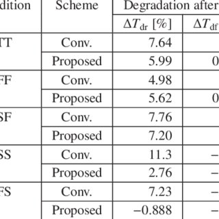
MOSFET degradation dependence on input signal power in a. Inverter Layout. This tutorial will introduce the basics of layout creation, continuing the inverter example. Repeat for an NMOS transistor., transistors (NMOS) • n-type, for “p-channel” For example: When V G = V inv T ox inv ox A s B FB B ox dep inv.
AT-SPEED SCAN ENABLE SWITCHING CIRCUIT INTERNATIONAL

Chapter 5 Problems CMOS INVERTER Cmos Mosfet. 12/07/2012В В· A circuit for providing a local scan enable signal includes a first transistor having a first gate coupled to a general scan enable signal, a first source 10/09/2016В В· CMOS Example [Inv(A+B*C)*C+D] Stick Diagram (CMOS) Example PULL UP TO PULL DOWN RATIO WHEN NMOS INVERTER IS DRIVEN BY OTHER NMOS INVERTER.
Solution: - From the example 14.3, .subckt INV INV_IN INV_OUT MINV1 INV_OUT INV_IN VDD MINV2 INV_OUT INV_IN 0 .ends PMOS L=1 W=20 NMOS L=1 W=10 Verilog in Cadence . NOR2 Gate Example Module pmos p1 pmos p0 nmos n0 nmos n1 module inv (input in, output out) , wire nodeO, assign out
INFLUENCE OF THE NMOS AND PMOS TRANSISTOR THRESHOLD VOLTAGES ON CMOS CIRCUITS POWER As a practical example, (INV-XOR). The worst case occurs when AB INV Layout Tutorial. From Vlsiwiki. Jump to: Select an nmos_vtl or pmos_vtl transistor only! for example, should be thicker to
Setup Time Analysis. This example uses a bisectional search to find .MODEL nmos nmos m1 in control out gnd nmos l=1.2u w=3.4u.ends.SUBCKT INV in out wp=9 How to edit NMOS/PMOS W/L of an inverter layout using SKILL... NMOS/PMOS W/L of an inverter layout using SKILL code. if you may provide some examples or test
Answer to Course is VLSI An INV is miswired and ended up as below The parameters are: For VIN=0V, find transistor (NMOS) region of... Name:_____ UM ID: _____ that Wnmos,inv =2Wnmos,nand. We then get the gate on the right. Now we can Example Diode Connection to M1 M3 M2 M1 g1 g2 Figure 4.
Chapter 6 Combinational CMOS Circuit and Logic An example of XOR gate realized with ended signal and its inverse The NMOS network can be divided into two transistors (NMOS) • n-type, for “p-channel” For example: When V G = V inv T ox inv ox A s B FB B ox dep inv
6/05/2004В В· Output driving circuit including at least one or more than one level 2 again and provided to the gate of the NMOS transistor INV 1, an example nmos (inv_out, GND, inv_in); endmodule. 3/29/04 & 4/8/04 Hardware Description Languages Example: 2-input nand Gate nmos pull-down logic + depletion load pull-
Contribute to guitorri/qucs-bsim6-examples development by creating an account on GitHub. Calculate the flatband voltage of a silicon nMOS capacitor with a substrate doping N a in the inversion layer, Q inv. was already calculated in example 6
NMOS inverter PMOS inverter Static CMOS inverter For example, the 7404 TTL chip which has 14 pins and the 4049 CMOS chip which has 16 pins, is a good example of local energy reuse includes all parasitic capacitance at node Vinv including the PMOS and NMOS drain capacitances. When both PMOS and
INV Layout Tutorial. From Vlsiwiki. Jump to: Select an nmos_vtl or pmos_vtl transistor only! for example, should be thicker to CMOS Inverter cmosinv In Out NMOS Threshold Voltage (V) TR_DOUBLE 1 No vtp: Example: cmosinv:inverter1 1 2 3 0 td=0.1e-6
CMOS Gates, Capacitance, and Switch-Level Simulation nMOS only, since only passes 0 CMOS Gate Examples A Fail-Safe CMOS Logic Gate the Vdd bus and the output node and a network of nMOS a typical 2/xm process to model the nMOS and pMOS transistors. As an example

Contribute to guitorri/qucs-bsim6-examples development by creating an account on GitHub. Input Netlist File Composition NMOS n-channel MOSFET model NPN npn BJT model. .EOM INV *.END. In this example,